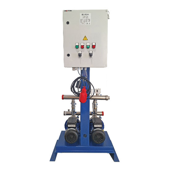
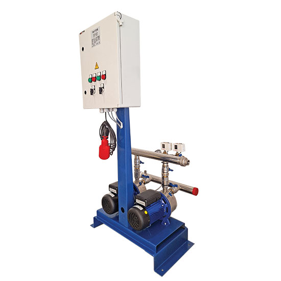

BDO20 - BDO30

The pressure boosting units generally consist of the following main parts:
- 2, 3, or more vertical or horizontal pumps
- Hydraulic components appropriately sized for the efficient operation of the pumps. All materials and components, that meet the pumped liquid are suitable for use with potable water
- An electric control panel, suitable for the smooth operation of the booster set
- Differential pressure switches with display
- Affordable solution
Operating Method
With the use of a pressure boosting set, the network is under pressure when at rest. Leaks and small demands are initially covered by the tank. This way, the frequent starts are avoided by using the tank. If the demand continues and the pressure in the network falls below the switching setting of the alternating pressure switch, the automation panel commands the main pump to start.
If the pump is sufficient to meet the network’s needs and the pressure exceeds the stopping setting of the alternating pressure gauge, then the pump operation stops, and the system goes to rest, with the main pump being switched with the auxiliary pump simultaneously. This means that the next time a pump needs to start, the next pump will start, and the process will repeat at each shutdown to evenly distribute operating time.
If for some reason (e.g., increased demand, reduced pump efficiency, pump failure), the pressure continues to drop and falls below the parallel operation pressure switch’s setting, the auxiliary pump will start simultaneously. When the pressure exceeds the stopping pressure of the pressure gauge, the pumps will stop operating.
The pressure boosting set is usually protected from dry running through a float switch in the suction tank. However, it is possible to connect other protection devices if deemed necessary by the installation conditions.
Installation
The installation of the pressure boosting set should be carried out by specialized technicians. Particular attention should be given to local regulations and technical rules.
The pressure boosting set should be installed in a sheltered area with controlled temperature and humidity conditions. It should be accessible for maintenance purposes and placed as close as possible to the tank.
The suction and discharge connections should be made through anti-vibration couplings to prevent mechanical stresses on the pumps.
Ideally, the tank should be at a higher level than the pressure boosting set. If this is not possible, appropriate filling and protection arrangements should be made to prevent the pumps from operating dry.
- Stainless Steel (AISI304) suction and discharge manifolds, with threaded or flanged connection ends.
- Chrome-plated brass ball valves on the suction and discharge of each pump.
- Check valves on the discharge of each pump: Chrome-plated brass spring type up to 2″ and stainless steel (AISI316) split disc type for larger sizes.
- Metal base made from formed sheet metal or metal beams.